 |
DirectOutput
DirectOutput framework R3 for virtual pinball cabinets.
|
|
DirectOutput
DirectOutput framework R3 for virtual pinball cabinets.
|
Artnet is a industry standard protocol used to control DMX lighting effects over ethernet. Using Art-Net it is possible to connect a very wide range of lighting effects like strobes or dimmer packs. There are tons of DMX controlled effects available on the market (from very cheap and small to very expensive and big). It might sounds a bit crazy, but with Art-net and DMX you could at least in theory control a whole stage lighting system (this would likely make you feel like Tommy in the movie).
To use Art-Net you will need a Art-Net node (unit that converts from ethernet to DMX protocol) and also some DMX controlled lighting effect. There are quite a few different Art-Net nodes available on the market and most of them should be compatible with the DirectOutput framework. For testing the Art-Net node sold by Ulrich Radig as a DIY kit was used.
Each Art-Net node/DMX universe supports 512 DMX channels and several Art-Net nodes controlling different DMX universes can be used in parallel.
If you want to read more about Art-net, visit the website of Artistic License. The specs for Art-net can be found in the Resources - User Guides + Datasheets section of the site.

A configuration section for ArtNet might resemble the following structure:
ArtNet has the following 3 configurable properties:
String containing broadcast address. If this parameter is not set the default broadcast address (255.255.255.255) will be used. Valid values are any IP adresses (e.g. 192.168.1.53).
The name of the item.
The number of the Dmx universe.
This output controller class is used to control the direct strip controller by Swisslizard.
The hardware of this controller is based on a Atmel microcontroller and a FT245R USB interface chip by FTDI. To ensure max performance all copde on the controller has been written in assembler.
WS2811 is a small controller chip which can controll a RGB led (256 PWM level on each channel) and be daisychained, so long cahins of LEDs (led strip are possible. The WS2812 understands the same protocoll as the WS2811, but is a RGB led with integrated controller chip which allows for even more dense populated RGB strips.
Those controller chips are controlled using a single data line (there is no clock line). The data has to be sent with a frequency of 800khz. 1 bits have a duration of 0.65uS high and 0.6uS low. 0 bits have a duration of 0.25uS high and 1uS low. A interuption in the dataflow triggers the controller chips to push the data in the shift register to the PWM outputs. Since the timing requirements are very strict it is not easily possible to output that signal directly from a computer with normal operating system. Thats why controllers like the one displayed below are needed.
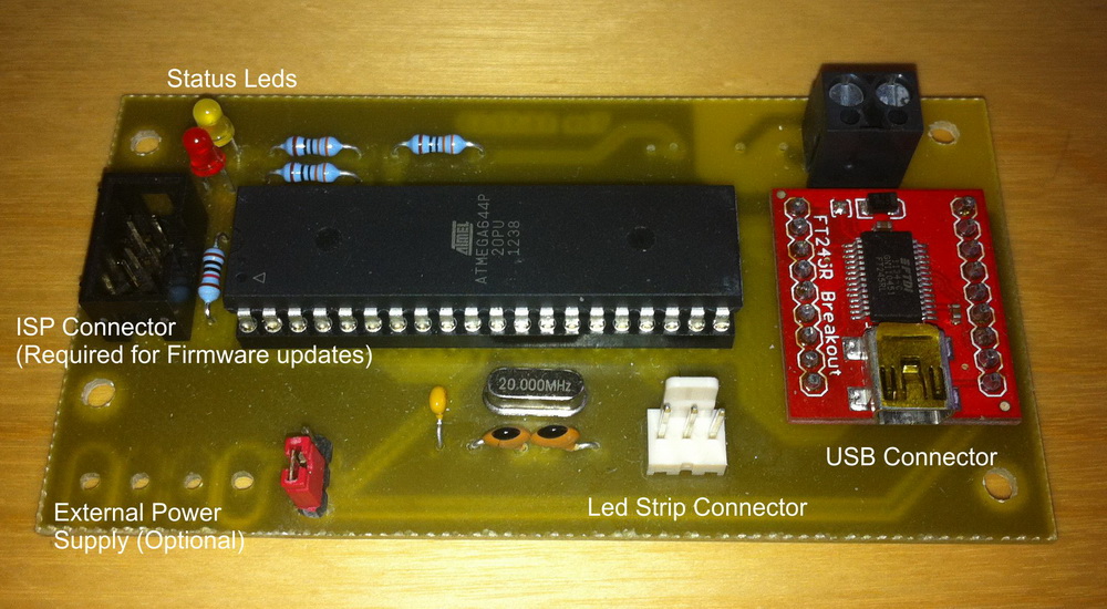
This is a image of my controller prototype with classical through the hole parts and a small breakoutboard by SparkFun. At the time of the release of DOF R2, the first prototypes of SMD version of the controller are in production. Check back in the forums for more information.
A configuration section for DirectStripController might resemble the following structure:
DirectStripController has the following 4 configurable properties:
The number of the WS2811 strip controller.
The name of the item.
The number of leds on the WS2811 based led strip.
true if data should be packed bore it is sent to the controller; otherwise false (default).
The Dude's Cab Controller is a all-in-one virtual pinball controller
It's based on the RP2040 processor, provide 32 inputs, accelerometer, plunger & Dof support. The Dof support provides 128 PWM outputs through up to 8 extension boards. Maximum intensity, Flipper logic, Chime logic & Gamma Correction are supported for all outputs Each outputs can also have its intensity lowered independently from the Dof values As for the Pinscape controller, the communication is fully supported through Hid In/Out protocol with multipart messages support The Dude's Cab controllers are registered in the Dof config tool from unit #90 to 94
A configuration section for DudesCab might resemble the following structure:
DudesCab has the following 4 configurable properties:
The mininimal interval between command in miliseconds. The default is 1ms, which is also the minimum, since it's the fastest that USB allows at the hardware protocol level.
The name of the item.
The unique unit number of the controller (Range 1-5).
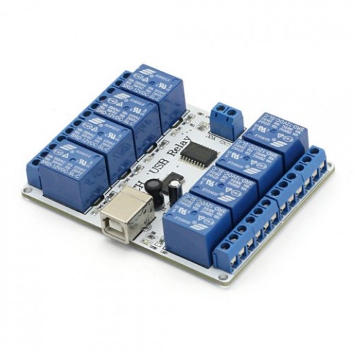
This is a generic output controller class which are based on the FT245R chip (http://www.ftdichip.com/Products/ICs/FT245R.htm). Only units using the chip in bitbang mode are supported by this output controller class. The SainSmart USB relay boards (http://www.sainsmart.com/arduino-compatibles-1/relay/usb-relay.html) are compatible with this output controller, but other hardware which is based on the same controller chip might be compatible as well. Generally controller units which is exclusively using the FT245R (no extra cpu on board) and having max. 8 output ports are likely to be compatible. Please let me know, if you have tested other hardware successfully, so I can ammend the docu.
Thanks go to DJRobX for his early implementation of a SainSmart output controller which was the starting point for the implementation of this class.
A configuration section for FT245RBitbangController might resemble the following structure:
FT245RBitbangController has the following 4 configurable properties:
The description string.
The unique Id of the device (Range 0-9).
The name of the item.
The serial number of the FT245R chip which is to be controlled.
The LedWiz is a easy to use outputcontroller with 32 outputs which all support 49 pwm levels with a PWM frequency of approx. 50hz. The LedWiz is able to drive leds and smaller loads directly, but will require some kind of booster for power hungery gadgets like big contactors or motors.

The DirectOutput framework does fully support the LedWiz and can control up to 16 LedWiz units.
The framework can automatically detect connected LedWiz units and configure them for use with the framework.
The LedWiz is made by GroovyGameGear and can by ordered directly on GroovyGamegears website, but also from some other vendors.
This unit was the first output controller which was widely used in the virtual pinball community and was the unit for which the legacy vbscript solution was developed. The DirectOutput framework replaces the vbscript solution, but can reuse the ini files which were used for the configuration of the tables. Please read ledcontrolfiles for more information.
The current implementation of the LedWiz driver uses a separate thread for every ledwiz connected to the system to ensure max. performance.

A configuration section for LedWiz might resemble the following structure:
LedWiz has the following 3 configurable properties:
The minimum interval between command in milliseconds
The name of the item.
The unique number of the LedWiz (Range 1-16).
This is a dummy output controller not doing anthing with the data it receives.
It is mainly thought as a sample how to implement a simple output controller.
Be sure to check the abstract OutputControllerBase class and the IOutputController interface for a better understanding.
A configuration section for NullOutputController might resemble the following structure:
NullOutputController has the following 1 configurable properties:
The name of the item.
The PacDrive is a simple output controller with 16 digital/on off outputs.
DOF supports a the use of 1 PacDrive unit. This unit can be detected and configured automatically. If auto configuration is used, the generated LedWizEquivalent toy for the PacDrive will have number 19. This means that ini files numbered with 19 are automatically used to configure a PicDrive unit.
The outputs are by default turned on when the PacDrive unit is powered up. This controller class will turn off the PacDrive outputs upon initialisation and when it is finished.
This unit is made and sold by Ultimarc.

A configuration section for PacDrive might resemble the following structure:
PacDrive has the following 1 configurable properties:
The name of the item.
The PacLed64 is a output controller with 64 outputs all supporting 256 pwm levels with a PWM frequency of 100khz. Since the outputs of the unit are constant current drivers providing 20ma each, leds can be connected directly to the outputs (no resistor needed), but booster circuits must be used to driver higher loads (e.g. Cree leds). Up to 4 PacLed64 controllers can be used with the DirectOutput framework.
The framework supports auto detection and configuration of these units. If auto config is used, two LedWizEquivalent toys are added for each connected PacLed64. The numbers of the LedWizEquivalents are based on the Id of the PacLed64. Id1=LedwizEquivalent 20+21, Id2=LedwizEquivalent 22+23, Id3=LedwizEquivalent 24+25, Id4=LedwizEquivalent 26+27. If the numbers of ini files used for the configuration match these numbers, they will be used to set up the effects for the table.
This unit is made and sold by Ultimarc.
The implemention of the PacLed64 driver uses a separate thread per connected unit to ensure max. performance.

A configuration section for PacLed64 might resemble the following structure:
PacLed64 has the following 4 configurable properties:
The unique Id of the PacLed64 (Range 1-4).
The name of the item.
The Ultimate I/O is a output controller with 96 outputs all supporting 256 pwm levels with a PWM frequency of 100khz. Since the outputs of the unit are constant current drivers providing 20ma each, leds can be connected directly to the outputs (no resistor needed), but booster circuits must be used to driver higher loads (e.g. Cree leds). Up to 2 Ultimate I/O (currently) can technically be used with the DirectOutput framework as supported by the PacDrive SDK (ask Ultimarc for firmware to program second ID), but this has not been tested nor confirmed.
The framework supports auto detection and configuration of these units. If auto config is used, two LedWizEquivalent toys are added for each connected Ultimate I/O. The numbers of the LedWizEquivalents are based on the Id of the PacUIO.
This unit is made and sold by Ultimarc.
The class was based on PacLed64.cs

A configuration section for PacUIO might resemble the following structure:
PacUIO has the following 2 configurable properties:
The unique Id of the PacUIO (Range 0-1).
The name of the item.
The Philips Hue family consists of Zigbee controlled lights and sensors using a bridge (the Philips Hue "hub").
The framework supports auto detection and configuration of these units.
Philips Hue is made and sold by Philips.
The class was based off PacUIO.cs, and implementation makes use of Q42.HueApi. As such it retains the 3-channel RGB style inputs, but converts that over to a single-channel #rrggbb hex string. Technically a single bridge can control about 50 lights x3 = 150 input channels (sensors are additionally ~60).
Before DOF can start communicating with the bridge it will need a valid key. To get a key off the bridge the Link-button on the bridge needs to be pressed, and an dof#pincab "user" needs to be registered in the bridge (whitelist) within 30 seconds. This will return a unique key (for instance "2P4R5UT6KAQcpOjFaqwLDrbikEEBsMIHY6z6Gjwg") which can then be used from that point on. The same registration on another bridge, or even the same, will create a new key.
To avoid duplicates / spamming the whitelist, and to avoid bugs crashing the bridge, currently this is the suggested approach for getting a key:
Step 1: set static IP to bridge Get IP of the bridge. Check your phone Hue App -> Settings -> My Bridge -> Network settings. It should default to DHCP. Change this to a static IP, and make note of it.
Step 2: whitelist DOF using a browser Open up the bridge API in a browser using your IP, example (replace IP with your static IP): http://10.0.1.174/debug/clip.html In the "CLIP API Debugger" it should say something like URL: "/api/1234/" with GET, PUT, POST, and DELETE-buttons. Copy & paste the following line into URL-field (not in your browser, but in the CLIP API Debugger): /api Copy & paste the following into the Message Body textfield: {"devicetype":"dof_app#pincab"} Next, run over to your bridge and press the physical Link button. You now have 30 seconds to run back to your browser, and press "POST"-button. You should now get a username in the Command Response textbox, for example: "ywCNFGOagGoJYtm16Kq4PS1tkGBAd3bj1ajg7uCk". Make note of this.
Step 3: add IP and key to Cabinet.xml Open up your Cabinet.xml, and add the following lines in the OutputControllers section, replacing the IP and key with your own: <PhilipsHueController><Name>PhilipsHueController</Name><BridgeIP>10.0.1.174</BridgeIP><BridgeKey>ywCNFGOagGoJYtm16Kq4PS1tkGBAd3bj1ajg7uCk</BridgeKey></PhilipsHueController>
Step 4: add lights using http://configtool.vpuniverse.com/login.php A bridge can handle about 50 lights. Each light will multiplex RGB (3 channels) on each send, similar to using RGB-buttons on a PacLed64 or UIO. To match your output channels to a specific light, use your Android / iOS Philips Hue app and decide which light you need to control. Each light should have a number in it, for instance "10. Hue lightstrip 1". That 10-number is the light ID. Mapped to the individual RGB-outputs in DOF Config Tool port assignments this means: ((light ID -1) * 3) + 1 = ((10 - 1) *3) + 1 = 27 +1 = 28, resulting in port 28, 29, 30 (R, G, B). If your light ID was 3, you'd map it to port 7, 8, 9. If your light ID was 1, you'd map it to port 1, 2, 3.
If you want to delete the key from your bridge, open up CLIP again, enter the API-URL (replace both keys with your own, they're the same used twice), then press DELETE: http://10.0.1.174/debug/clip.html /api/ywCNFGOagGoJYtm16Kq4PS1tkGBAd3bj1ajg7uCk/config/whitelist/ywCNFGOagGoJYtm16Kq4PS1tkGBAd3bj1ajg7uCk
///
A configuration section for PhilipsHueController might resemble the following structure:
PhilipsHueController has the following 5 configurable properties:
Gets or sets active bridge device type / "app id". For an API to communicate with a Philips Hue bridge, a first-time pairing mode using BridgeDeviceType as ID is required. Once this pairing is complete, a BridgeKey will be generated. To start communicating with a bridge, BridgeIP and BridgeKey is required as handshake before controlling lights. Ideally this should not be changed / set, only read during initial pairing mode to get the actual key.
Gets or sets active bridge IP.
Gets or sets active bridge user key.
The unique Id of the PhilipsHueController (Range 0-1).
The name of the item.
PinControl is a Arduniobased output controller by http://www.vpforums.org/index.php?showuser=79113 Is has 4 pwm output, 6 digital outputs. DOF supports any number of these controllers. Outputs 1,8,9,10 are pwm outputs. Outputs 2,3,4,5,6,7 are digital outputs.
A configuration section for PinControl might resemble the following structure:
PinControl has the following 2 configurable properties:
The COM port for the controller.
The name of the item.
The PinOne Controller is a free for non commercial use software/hardware project based on the inexpensive, easy to use Arduino microcontroller development platform. Almost any Arduino based board will work with the software, but the Cleveland Software Design PinOne board is specifically designed to work with the software and has all the hardware components already added into it. The ClevelandSoftwareDesign PinOne controller has 63 outputs built into the board that can be utilized by DOF. 31 outputs are available in the board and an additional 32 outputs can be added via expansion boards. DOF can automatically detect connected PinOne controllers and configure them for use with the framework.
A configuration section for PinOne might resemble the following structure:
PinOne has the following 5 configurable properties:
The minimal interval between command in milliseconds. The default is 1ms, which is also the minimum, since it's the fastest that USB allows at the hardware protocol level.
The minimal interval between command in milliseconds. The default is 1ms, which is also the minimum, since it's the fastest that USB allows at the hardware protocol level.
The name of the item.
The unique unit number of the controller (Range 1-16).
The Pinscape Controller is an open-source software/hardware project based on the inexpensive and powerful Freescale FRDM-KL25Z microcontroller development platform. It provides a full set of virtual pinball cabinet I/O features, including analog plunger, accelerometer nudging, key/button input, and a flexible array of PWM outputs.
For DOF purposes, we're only interested in the output controller features; all of the input features are handled through the standard Windows USB joystick drivers. The output controller emulates an LedWiz, so legacy LedWiz-aware software can access its basic functionality. However, the Pinscape controller has expanded functionality that the LedWiz protocol can't access due to its inherent design limits. To allow access to the expanded functionality, the Pinscape controller uses custom extensions to the LedWiz protocol. This DirectOutput framework module lets DOF use the extended protocol to take full advantage of the extended features. First and most importantly, the Pinscape controller can support many more output channels than a real LedWiz. In fact, there's no hard limit to the number of channels that could be attached to one controller, although the practical limit is probably about 200, and the reference hardware design provides up to about 60. The extended protocol allows for about 130 channels, which is hopefully well beyond what anyone will be motivated to actually build in hardware. Second, the extended protocol provides 8-bit PWM resolution, whereas the LedWiz protocol is limited to 49 levels (about 5-1/2 bit resolution). DOF uses 8-bit resolution internally, so this lets devices show the full range of brightness levels that DOF can represent internally, for smoother fades and more precise color control in RGB devices (or more precise speed control in motors, intensity control in solenoids, etc).
DOF uses the extended protocol, so it can fully access all of the expanded features. Legacy software that uses only the original LedWiz protocol (e.g., Future Pinball) can still recognize the device and access the first 32 output ports, using 49-level PWM resolution.
DOF can automatically detect connected Pinscape controllers and configure them for use with the framework.
The Pinscape Controller project can be found on mbed.org.
A configuration section for Pinscape might resemble the following structure:
Pinscape has the following 4 configurable properties:
The minimal interval between command in milliseconds. The default is 1ms, which is also the minimum, since it's the fastest that USB allows at the hardware protocol level.
The name of the item.
The unique unit number of the controller (Range 1-16).
The Pinscape Pico controller is an open-source software/hardware project based on the Raspberry Pi Pico. Pinscape Pico is a sequel to the original Pinscape Controller for KL25Z, providing a full set of pinball cabinet I/O features, including analog plunger, accelerometer nudging, key/button input, and a flexible array of PWM outputs.
DOF is only concerned with the Pinscape Pico's output controller features. Pinscape Pico provides a custom HID interface for the output controller functions, which DOF uses to send commands to the device. Refer to USBProtocol/FeedbackControllerInterface.h in the Pinscape Pico source repository for documentation on the protocol.
DOF can automatically detect connected Pinscape Pico units (by scanning the set of live HID instances) and configure them for use with the framework. No manual user configuration is required to use these devices.
A configuration section for PinscapePico might resemble the following structure:
PinscapePico has the following 4 configurable properties:
The minimal interval between command in milliseconds. The default is 1ms, which is also the minimum, since it's the fastest that USB allows at the hardware protocol level.
The name of the item.
The unique unit number of the controller (Range 1-16).
The SSFImpactor supports for using common audio bass shakers to emulate/simulate contractors/solenoids in a Virtual Pinball Cabinet.
It presents itself as a full set of contactors, etc for assignment via DOF Config. Support, hardware suggestions, layout diagrams and the just about friendliest people in the hobby can be found here: https://www.facebook.com/groups/SSFeedback/
For help specifically with SSFImpactor look fo Kai "MrKai" Cherry.
A configuration section for SSFImpactController might resemble the following structure:
SSFImpactController has the following 13 configurable properties:
One of the ManagedBass.Speaker* enums, or None
One of the ManagedBass.Speaker* enums, or None
Number representing the Device
One of the ManagedBass.Speaker* enums, i.e.
Number, 0 - 100
true or false
The name of the item.
The TeensyStripController is used to control up to 8 WS2811/WS2812 based ledstrips with up to 1100 leds per strip which are connected to a Teensy 3.1, 3.2 or later.
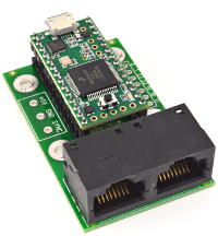
The best place to get the hardware is probably the website of the Teennsy inventor, where you can buy the Teensy boards (check if newer versions are available) and also a adapter board which allows for easy connection of up to 8 led strips. There are also numerous other vendors of Teensy hardware (just ask Google).
The firmware for the Teensy based ledstrip controller is based on a slightly hacked version of Paul Stoffregens excellent OctoWS2811 LED Library which can easily drive up to 1100leds per channel on a Teensy 3.1 or later. More information on the OctoWS2811 lib can be found on the Teensy website, on Github and many other places on the internet.
Ready to use, compiled firmware files can be downloaded from the Github page for the TeensyStripController, the source code for the firmware is available on Github as well.
A configuration section for TeensyStripController might resemble the following structure:
TeensyStripController has the following 21 configurable properties:
The baud rate of the Com port (by default 9600) the Teensy board is using.
The DataBits of the Com port (by default 8) the Teensy board is using.
The COM port wait after write in milliseconds (Valid range 50-500ms, default: 50ms).
The COM port wait before read in milliseconds (Valid range 20-500ms, default: 20ms).
The name of the Com port (typicaly COM{Number}) the Teensy board is using.
The COM port wait on opening in milliseconds (Valid range 50-5000ms, default: 50ms).
The Parity of the Com port (by default Parity.None) the Teensy board is using.
The property ComPortParity accepts the following values:
The StopBits of the Com port (by default StopBits.One) the Teensy board is using.
The property ComPortStopBits accepts the following values:
The COM port timeout in milliseconds (Valid range 1-5000ms, default: 200ms).
The name of the item.
The number of leds on the ledstrip connected to channel 1 of the Teensy.
The number of leds on the ledstrip connected to channel 10 of the Teensy.
The number of leds on the ledstrip connected to channel 2 of the Teensy.
The number of leds on the ledstrip connected to channel 3 of the Teensy.
The number of leds on the ledstrip connected to channel 4 of the Teensy.
The number of leds on the ledstrip connected to channel 5 of the Teensy.
The number of leds on the ledstrip connected to channel 6 of the Teensy.
The number of leds on the ledstrip connected to channel 7 of the Teensy.
The number of leds on the ledstrip connected to channel 8 of the Teensy.
The number of leds on the ledstrip connected to channel 9 of the Teensy.
The WemosD1MPStripController is a Teensy equivalent board called Wemos D1 Mini Pro (also known as ESP8266), it's cheaper than the Teensy and can support the same amount of Ledstrip and leds per strip.
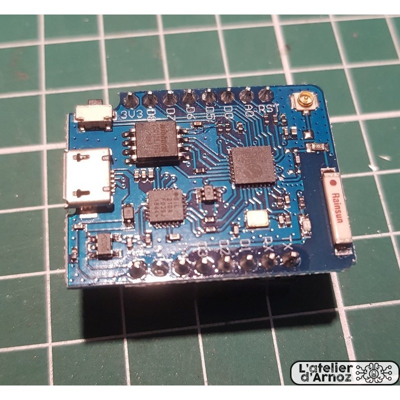
The Wemos D1 Mini Pro firmware made by aetios50, peskopat and yoyofr can be found there aetios50 Github page
You can also find a tutorial (in french for now) explaining the flashing process for the Wemos D1 Mini Pro using these firmware Arnoz' lab Wemos D1 flashing tutorial
There is a great online tool to setup easily both Teensy and Wemos D1 based ledstrips (an english version is also available) Arnoz' cacabinet generator
A configuration section for WemosD1MPStripController might resemble the following structure:
WemosD1MPStripController has the following 24 configurable properties:
The baud rate of the Com port (by default 9600) the Teensy board is using.
The DataBits of the Com port (by default 8) the Teensy board is using.
The COM port wait after write in milliseconds (Valid range 50-500ms, default: 50ms).
The COM port wait before read in milliseconds (Valid range 20-500ms, default: 20ms).
The name of the Com port (typicaly COM{Number}) the Teensy board is using.
The COM port wait on opening in milliseconds (Valid range 50-5000ms, default: 50ms).
The Parity of the Com port (by default Parity.None) the Teensy board is using.
The property ComPortParity accepts the following values:
The StopBits of the Com port (by default StopBits.One) the Teensy board is using.
The property ComPortStopBits accepts the following values:
The COM port timeout in milliseconds (Valid range 1-5000ms, default: 200ms).
The name of the item.
The number of leds on the ledstrip connected to channel 1 of the Teensy.
The number of leds on the ledstrip connected to channel 10 of the Teensy.
The number of leds on the ledstrip connected to channel 2 of the Teensy.
The number of leds on the ledstrip connected to channel 3 of the Teensy.
The number of leds on the ledstrip connected to channel 4 of the Teensy.
The number of leds on the ledstrip connected to channel 5 of the Teensy.
The number of leds on the ledstrip connected to channel 6 of the Teensy.
The number of leds on the ledstrip connected to channel 7 of the Teensy.
The number of leds on the ledstrip connected to channel 8 of the Teensy.
The number of leds on the ledstrip connected to channel 9 of the Teensy.
true if the commands are sent
true, will ask for the test at connection stage
true, use the compression when it worth it
The WS2811StripController class is just a simple wrapper around the DirectStripController class. It is only here to allow the use of old configs. Use the DirectStripController class for your configs.
A configuration section for WS2811StripController might resemble the following structure:
WS2811StripController has the following 4 configurable properties:
The number of the WS2811 strip controller.
The name of the item.
The number of leds on the WS2811 based led strip.
true if data should be packed bore it is sent to the controller; otherwise false (default).
 1.14.0